Sidebar
Table of Contents
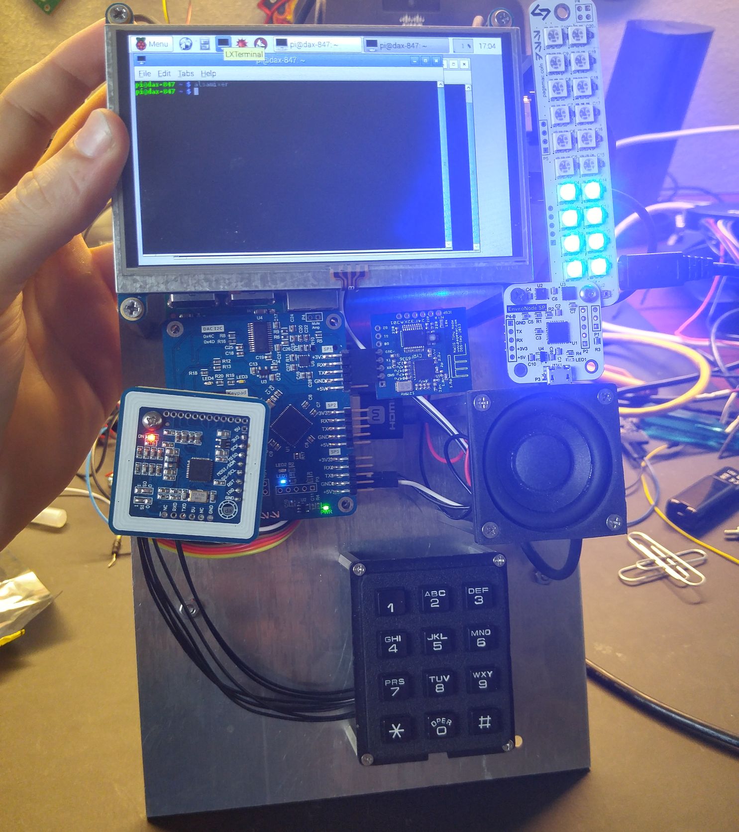
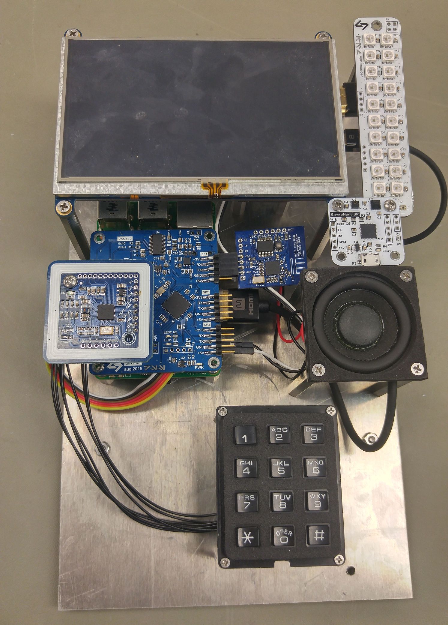
Raspberry Pi Security System Panel
After a few months of designing some boards and buying hardware, I have put together a prototype for my next generation security system.
Although I have been working on my security system for a couple of years, I've already been planning the next version of the system. In fact, much of the design work for the hardware in this post started in early 2015. I'm still developing my current system, but eventually everything will integrate into the new system.

The current system uses some LED panels with 4 buttons at each door to control some basic system functionality. This wasn't ever intended to be the “final” door panel, but I needed something to throw together quickly at the time that could at least tie me over until I designed something better. Well, over a year later I'm still using the same panels as the scope of my desired panel has grown.
Originally, I wanted something small and smiple. I knew I wanted a screen and buttons on the panel. I wasn't really a fan of the standard two-line LCD displays, however I do like black and white OLED panels. But I haven't been able to find any of a decent size. Eventually I decided to try out the PiTFT display from Adafruit, which is a pretty great screen. I even put together a pretty cool prototype touchscreen interface using pygame. Since my new panel was using a Raspberry Pi now and had a touchscreen, I needed a good speaker, audio amp, and hey why not a matrix keypad?
While I was thinking along this path, I realized how terrible the audio output is on the Raspberry Pi. This led me to develop the PCM2707 USB DAC + Amp and I2S Audio DAC + Amp. I decided I definitely wanted to use an I2S audio solution with a Pi hat, but this would be difficult to mix with the PiTFT.
It was about this time I found the Adafruit 5" HDMI Touchscreen. The screen was bigger, used HDMI, and had a better mounting solution. I just said screw it at this point, I'm just going to make a big awesome panel (inspired by awesome video game security panels). I figured I could make a Javscript web interface so that the system could be controlled from a panel or any other computer. I decided to add a new LED strip for lights, an NFC reader/writer, and a new environmental sensor.
A few of my friends have pointed out “why not just use an android phone or tablet? It has most of those features.” The answer is, of course, it's much more fun to build it yourself! :)
Below is a description of the hardware modules. I haven't written most of the software or firmware for these devices, but eventually once I've had a chance to develop them a little more, I will write more detailed documentation and upload the design files.
dax-hat
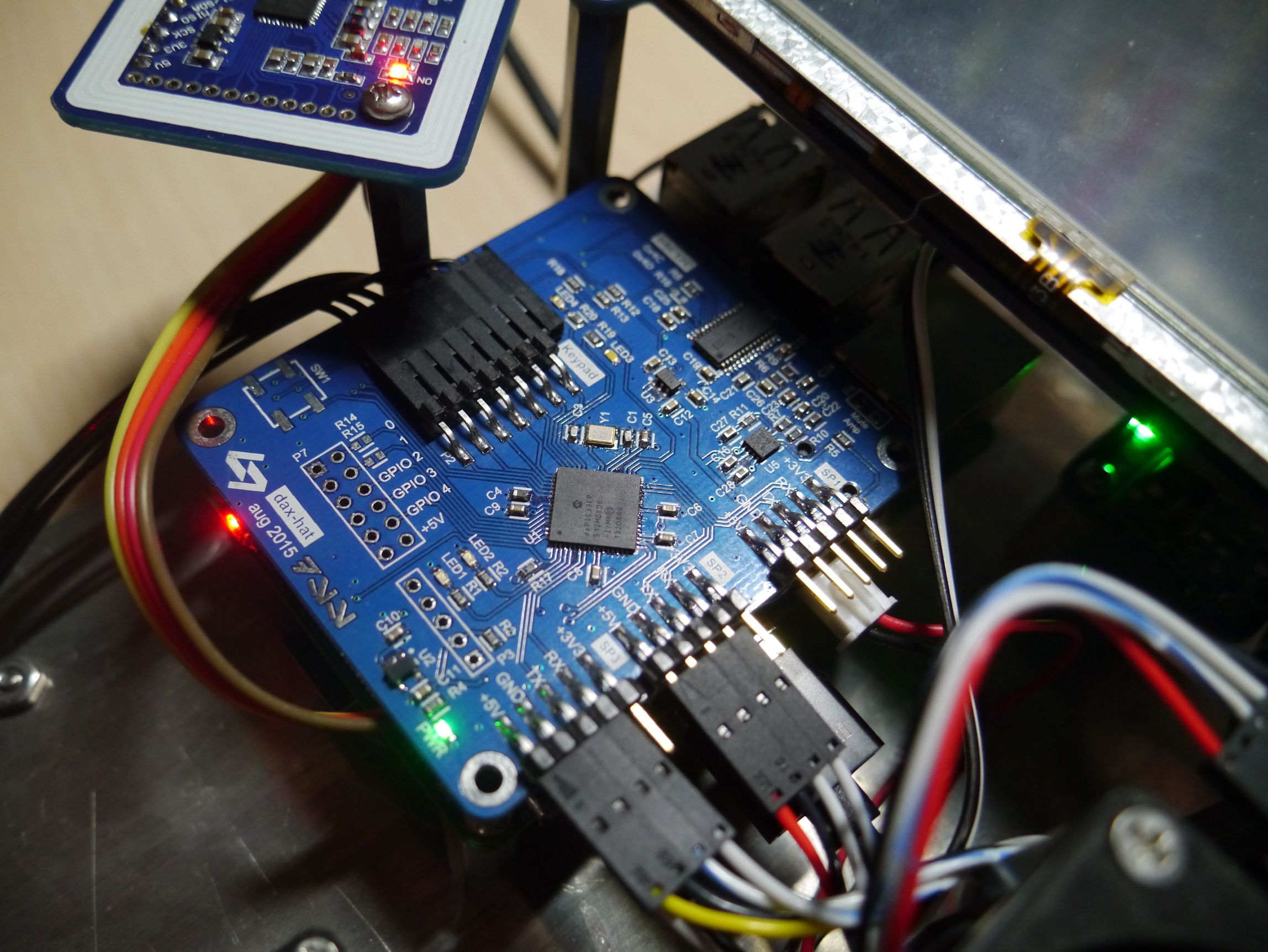
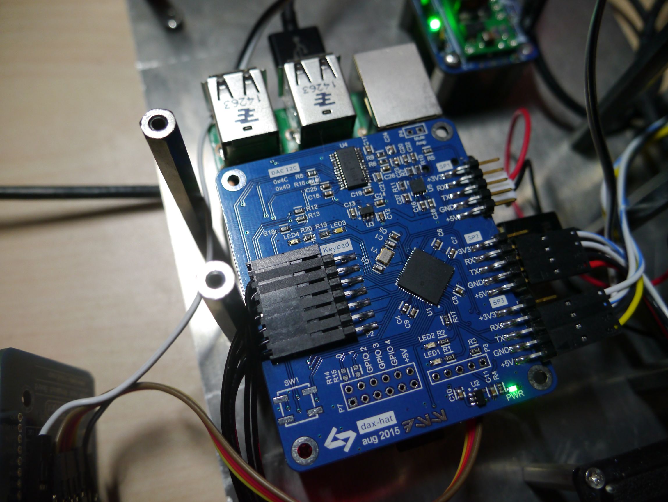
This hat is the central board that connects most of the components together. It is based around a dsPIC33EP512MC806 microcontroller, which communicates with the Raspberry Pi as well as 3 other devices over 3V3 serial. The PIC acts as a serial multiplexer so that the Python code on the Pi can communicate with the other 3 devices individually, as well as send commands to the micro itself. The micro also reads the matrix keypad.
Separate from the microcontroller, I used a PCM5122 as an I2S audio DAC. The PCM5122 is controlled over I2C, which is connected to the Raspberry Pi. I tested with drivers for the IQaudio DAC+ and the HiFiBerry DAC+, using these procedures, both of which use the same PCM5122. I'm not really sure if there is much of a difference between the two drivers, other than a different I2C address. The lower two bits of the 7 bit I2C address is determined by two pins on the PCM5122 that can be pulled high or low. IQaudio is kind enough to mention the I2C address used on their board (0x4C). HiFiBerry doesn't specify the address used, but by looking at high resolution closeups of their board (and trial and error), I determined it is 0x4D. The layout and design is based on the PCM5122 reference design. I also use a TPA2006D mono audio amp, which drives the panel's speakers. There is also a 3.5mm audio output jack before the amp, so it could be plugged into another system that already has an amp.
Power for the Raspberry Pi is provided through this board. I used a really thick trace and an extra 100uF cap.
Finally, there are headers on the bottom of the board that connect to the Raspberry Pi SPI pins, used for the NFC reader.
led-strip
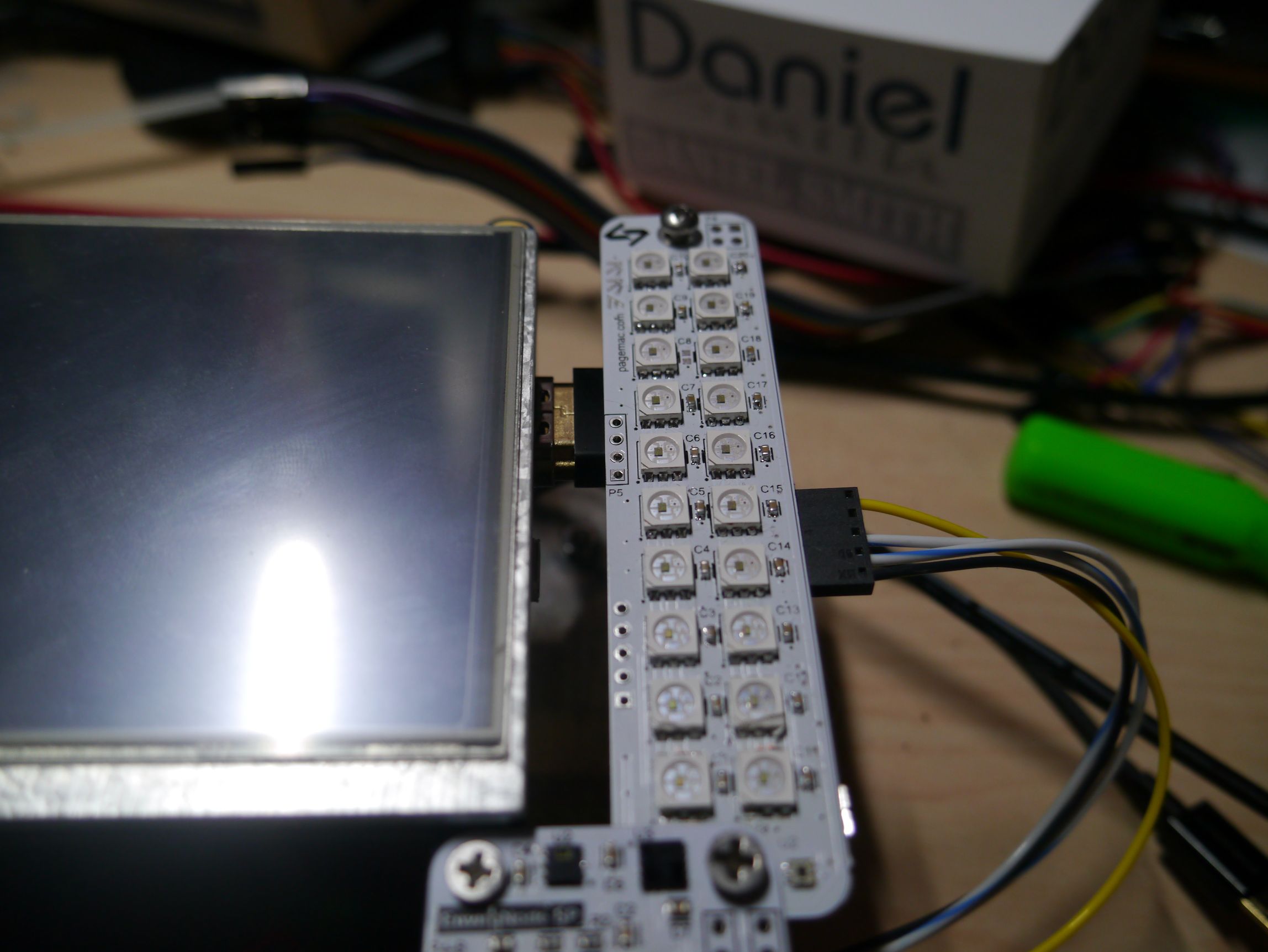
The led-strip is based on my LED_Panel design. Not really sure why I made this, I mostly just wanted some cool LED's to go with it.
However, instead of using an Arduino (ATmega328P) and the WS2812 LEDs, I switched to using a PIC and the APA102 LEDs. The APA102 RGB LEDs are really cool because they have a clock and data pin instead of a single data pin. So no complicated timing required, you can just use SPI! Read more about them here!
The size of this board is designed to match the size of the touchscreen.
EnviroNode SP
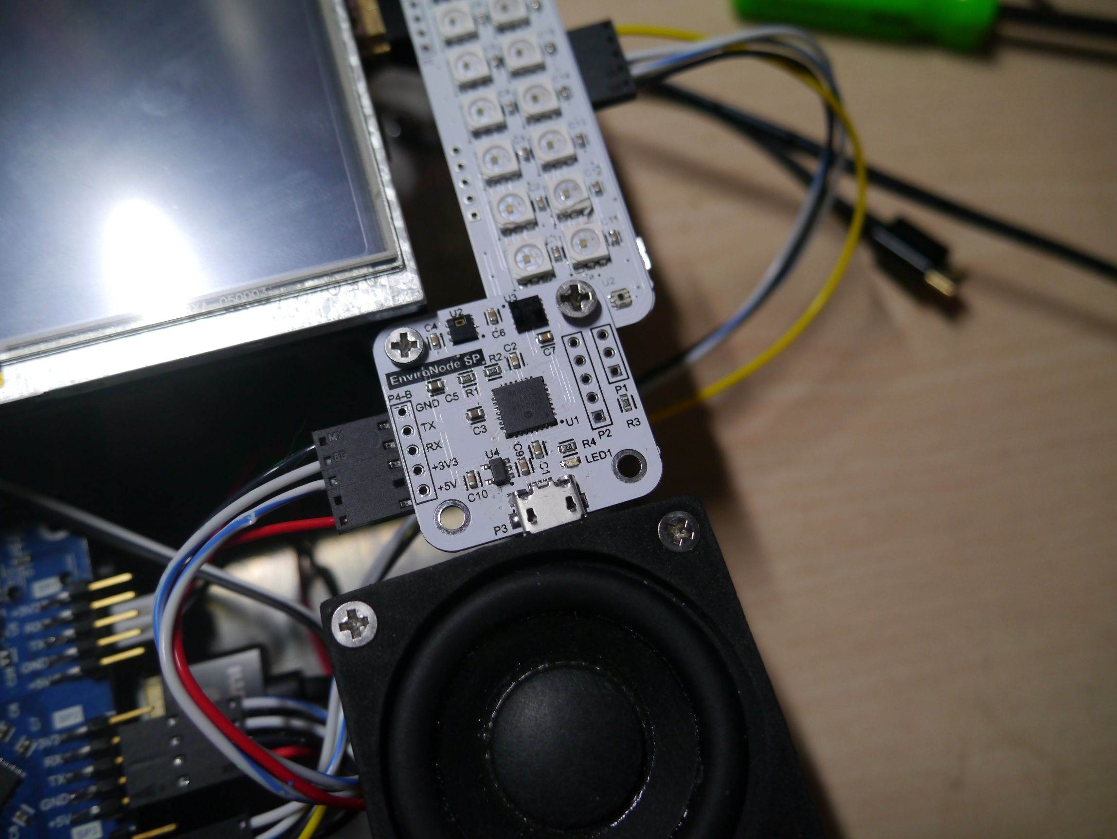
The EnviroNodeSP is based on my EnviroNode design. It uses the same digital temp and humidity sensor, but drops the analog light sensor for the much beefier VCNL4010. Except this isn't just a light sensor, it's an active infrared proximity sensor as well. My hope is that the panel can respond to hand waving in front of it in addition to ambient light detection.
SP stands for “sensor package”, which was the code name for this module in some of my earlier drawings before I knew what it was going to be.
I haven't coded any firmware for this board other than blinking an LED, so hopefully the VCNL4010 is as cool as I think it is.
PN532 NFC

I got this PN532 NFC module from eBay. There's a few different options on eBay. I would have liked to use Adafruit's module since I am using their Python code, but their module is freaking huge and too expensive. This one (branded “Deek Robot”) is much smaller, cheaper, and works just the same as far as I can tell.
I have done some basic testing with the module and it works great with Adafruit's Python code. For now I will use it just for basic authentication, but I have some ideas about dynamic NFC tags that could make this feature more interesting…
Power Module
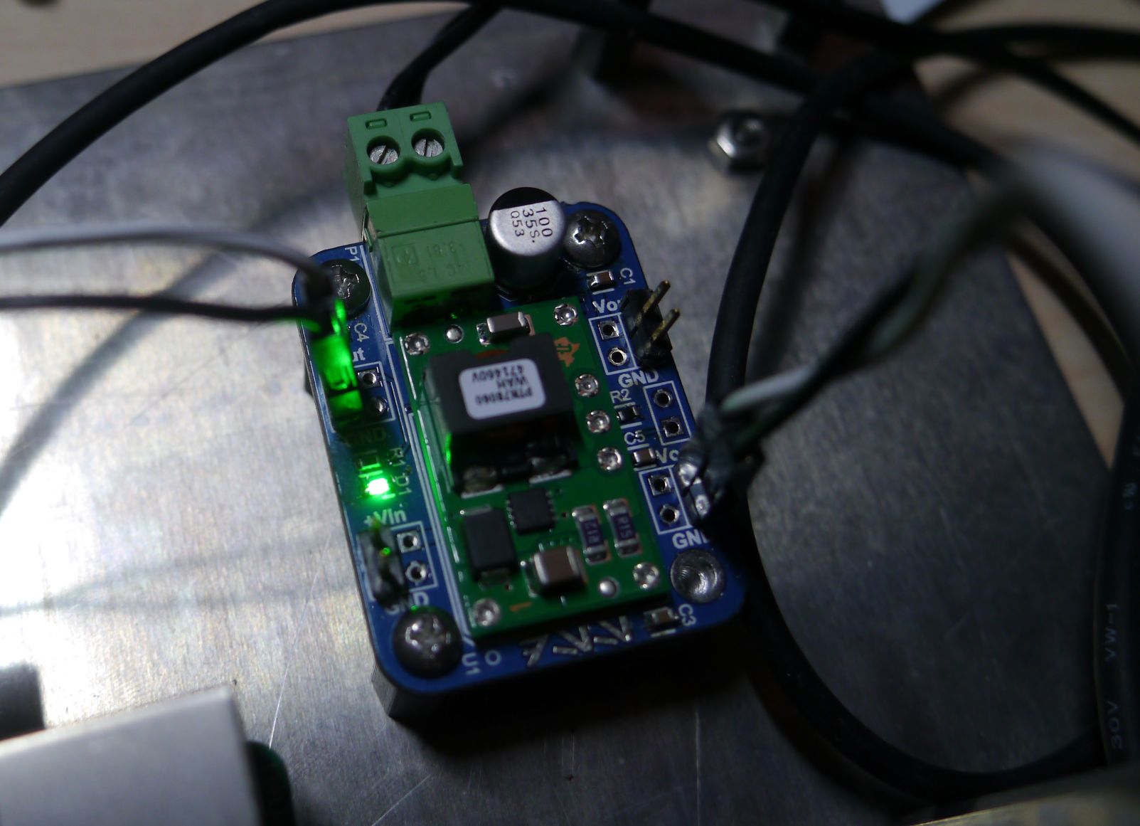
Powering all of these modules was getting interesting as the total current consumption increased. Originally I was using some high quality 2.1amp phone chargers, but the voltage was sagging too much with the Pi, hat, touchscreen, audio amp, etc. I decided I'd rather provide ~12V somewhere and switch it down.
I built a break-out module for the PTN78060WAH switching regulator. The TI modules are little expensive but they are truly fantastic. The 3 amps is more than enough to power all the systems. Stupidly, I didn't include a breakout for the sense pins, which would have made even more sense. But by routing power to each of the boards individually, everything works well. I'll investigate the power systems a little more.
Speaker and Keypad
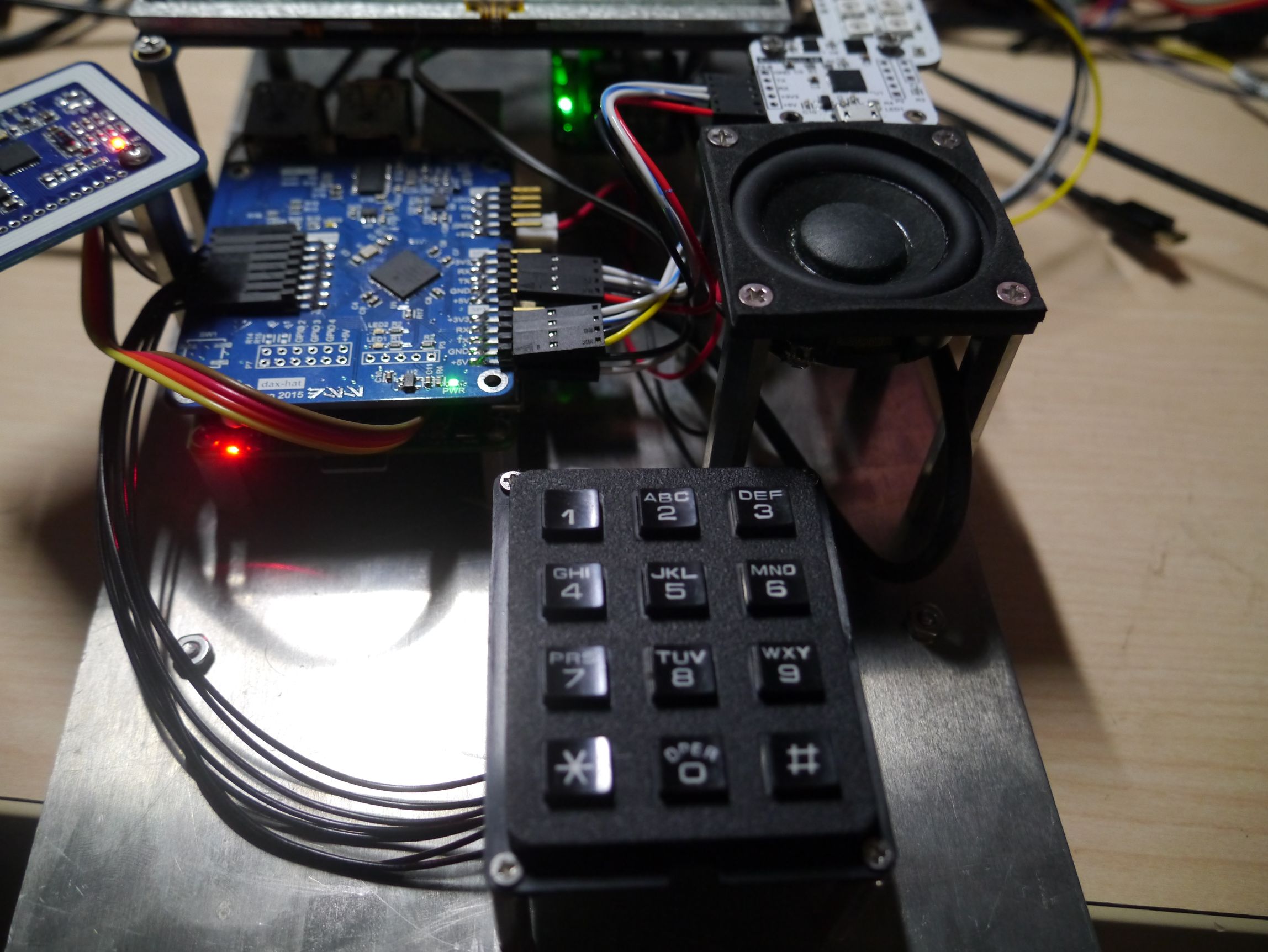
I got the Dayton Audio 1-7/8" full-range driver from PartsExpress. I need to make a proper enclosure for the speaker, as it doesn't work too well without a box. There's a few other drivers on DigiKey I was thinking about checking, but I need to do full testing with this driver first.
The Matrix Keypad from Adafruit is pretty simple. It would be nice to find a metal keypad, but this will work for now.
What's next?
Next up, I need to build an aluminum chassis for everything! Followed by writing lots of firmware and software…
Page Tools
