Sidebar
Table of Contents
Arduino Wiegand Decoder for HID RFID Reader
I wrote this Arduino sketch as a follow-up to my PIC Wiegand decoder. That article goes into a lot more detail about the Wiegand protocol and how it works. However, it was one of my first microcontroller projects. The code wasn't great and the hardware was a custom PIC18 development board. If you're starting from scratch, it wouldn't be particularly easy to re-implement that code. So, I made a Wiegand decoder using the Arduino, since it's a very popular development platform.
Hardware and Connections
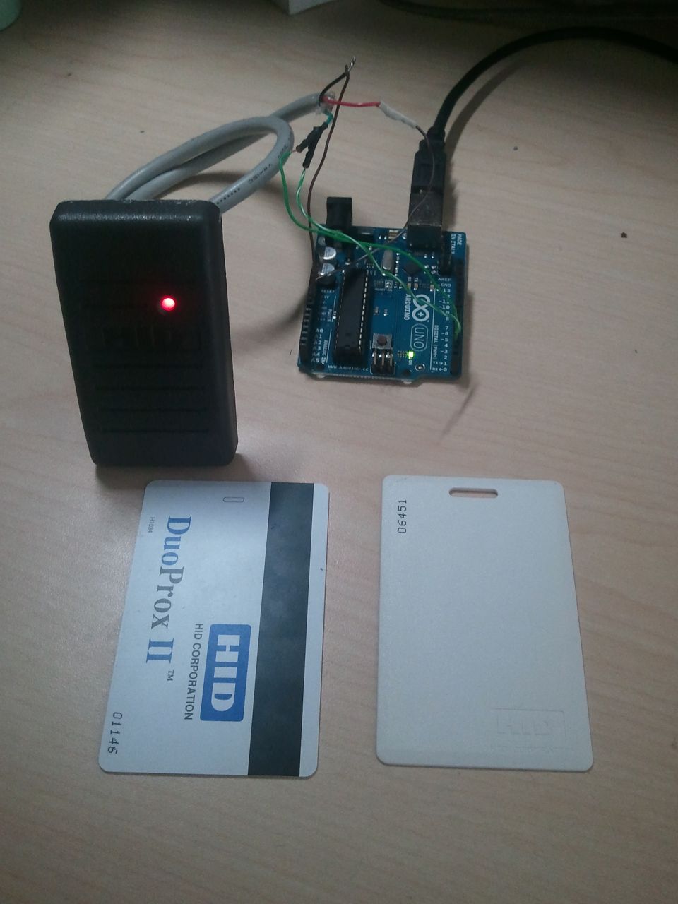
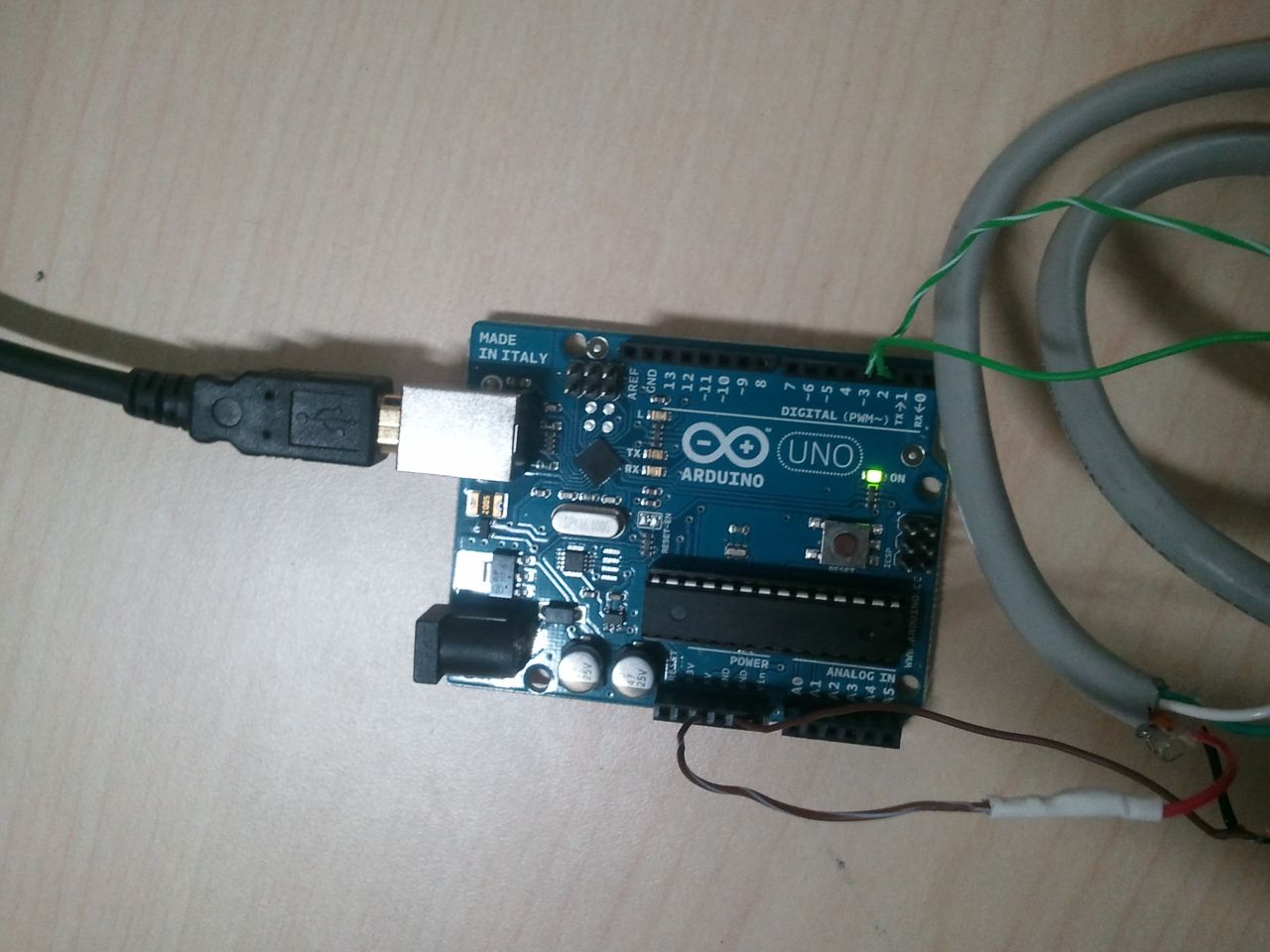
The only hardware required is an Arduino Uno (sub for your preferred board) and an HID reader. Pictured is a smaller ProxPoint Plus, but any 125 kHz HID proximity reader should work. You may need to provide power externally.
- Connect the red wire (power) to 5V
- Connect the black wire to ground
- Connect the green wire (DATA0) to Digital Pin 2 (INT0)
- Connect the white wire (DATA1) to Digital Pin 3 (INT1)
Operation
This program will decode the wiegand data from a HID RFID Reader (or, theoretically, any other device that outputs Wiegand data). The Wiegand interface has two data lines, DATA0 and DATA1. These lines are normally held high at 5V. When a 0 is sent, DATA0 drops to 0V for a few microseconds. When a 1 is sent, DATA1 drops to 0V for a few microseconds. There is usually a few milliseconds between the pulses.
Each of the data lines are connected to hardware interrupt lines. When one drops low, an interrupt routine is called and adds the bits to a buffer. Since the number of bits on a card is variable, the Arduino must wait until it hasn't received any bits for some time. After this time of not receiving any bits, the Arduino will decode the data and output it over serial. I've only added the 26 bit and 35 bit formats, but you can easily add more. For more information about data formats, check out this page.
This was my second Arduino project, and I'm always amazed at how simple it is to get things up and running. It only took me an hour! I especially like having easy functions such as attachInterrupt, as it's much easier than hunting down registers on a PIC or boot.tpl files on a PSoC.
Source
- arduino_hid_wiegand.ino
/*
 * HID RFID Reader Wiegand Interface for Arduino Uno
 * Written by Daniel Smith, 2012.01.30
 * www.pagemac.com
 *
 * This program will decode the wiegand data from a HID RFID Reader (or, theoretically,
 * any other device that outputs weigand data).
 * The Wiegand interface has two data lines, DATA0 and DATA1.  These lines are normall held
 * high at 5V.  When a 0 is sent, DATA0 drops to 0V for a few us.  When a 1 is sent, DATA1 drops
 * to 0V for a few us.  There is usually a few ms between the pulses.
 *
 * Your reader should have at least 4 connections (some readers have more).  Connect the Red wire
 * to 5V.  Connect the black to ground.  Connect the green wire (DATA0) to Digital Pin 2 (INT0).
 * Connect the white wire (DATA1) to Digital Pin 3 (INT1).  That's it!
 *
 * Operation is simple - each of the data lines are connected to hardware interrupt lines.  When
 * one drops low, an interrupt routine is called and some bits are flipped.  After some time of
 * of not receiving any bits, the Arduino will decode the data.  I've only added the 26 bit and
 * 35 bit formats, but you can easily add more.

*/


#define MAX_BITS 100                 // max number of bits
#define WEIGAND_WAIT_TIME  3000      // time to wait for another weigand pulse.

unsigned char databits[MAX_BITS];    // stores all of the data bits
unsigned char bitCount;              // number of bits currently captured
unsigned char flagDone;              // goes low when data is currently being captured
unsigned int weigand_counter;        // countdown until we assume there are no more bits

unsigned long facilityCode=0;        // decoded facility code
unsigned long cardCode=0;            // decoded card code

// interrupt that happens when INTO goes low (0 bit)
void ISR_INT0()
{
  //Serial.print("0");   // uncomment this line to display raw binary
  bitCount++;
  flagDone = 0;
  weigand_counter = WEIGAND_WAIT_TIME;

}

// interrupt that happens when INT1 goes low (1 bit)
void ISR_INT1()
{
  //Serial.print("1");   // uncomment this line to display raw binary
  databits[bitCount] = 1;
  bitCount++;
  flagDone = 0;
  weigand_counter = WEIGAND_WAIT_TIME;
}

void setup()
{
  pinMode(13, OUTPUT);  // LED
  pinMode(2, INPUT);     // DATA0 (INT0)
  pinMode(3, INPUT);     // DATA1 (INT1)

  Serial.begin(9600);
  Serial.println("RFID Readers");

  // binds the ISR functions to the falling edge of INTO and INT1
  attachInterrupt(0, ISR_INT0, FALLING);
  attachInterrupt(1, ISR_INT1, FALLING);


  weigand_counter = WEIGAND_WAIT_TIME;
}

void loop()
{
  // This waits to make sure that there have been no more data pulses before processing data
  if (!flagDone) {
    if (--weigand_counter == 0)
      flagDone = 1;
  }

  // if we have bits and we the weigand counter went out
  if (bitCount > 0 && flagDone) {
    unsigned char i;

    Serial.print("Read ");
    Serial.print(bitCount);
    Serial.print(" bits. ");

    // we will decode the bits differently depending on how many bits we have
    // see www.pagemac.com/azure/data_formats.php for mor info
    if (bitCount == 35)
    {
      // 35 bit HID Corporate 1000 format
      // facility code = bits 2 to 14
      for (i=2; i<14; i++)
      {
         facilityCode <<=1;
         facilityCode |= databits[i];
      }

      // card code = bits 15 to 34
      for (i=14; i<34; i++)
      {
         cardCode <<=1;
         cardCode |= databits[i];
      }

      printBits();
    }
    else if (bitCount == 26)
    {
      // standard 26 bit format
      // facility code = bits 2 to 9
      for (i=1; i<9; i++)
      {
         facilityCode <<=1;
         facilityCode |= databits[i];
      }

      // card code = bits 10 to 23
      for (i=9; i<25; i++)
      {
         cardCode <<=1;
         cardCode |= databits[i];
      }

      printBits();
    }
    else {
      // you can add other formats if you want!
     Serial.println("Unable to decode.");
    }

     // cleanup and get ready for the next card
     bitCount = 0;
     facilityCode = 0;
     cardCode = 0;
     for (i=0; i<MAX_BITS; i++)
     {
       databits[i] = 0;
     }
  }
}

void printBits()
{
      // I really hope you can figure out what this function does
      Serial.print("FC = ");
      Serial.print(facilityCode);
      Serial.print(", CC = ");
      Serial.println(cardCode);
}
Writeup: January 2012
Page Tools
