Sidebar
Table of Contents
Raspberry Pi 10 Hz GPS / IMU Data Logger
When I worked at the Georgia Tech Research Institute, I was part of a team that frequently performed field tests that required knowing the precise position and orientation of equipment that was flying in an aircraft or mounted to a vehicle. We had professional equipment that would capture this data using GPS and an IMU (inertial measurement unit), but it was often inconvenient to access this data; either it needed to be removed from the aircraft/vehicle and connected to a computer with special software to download the data to a USB drive, or maybe it needed to be converted into a different format (such as raw NMEA strings to CSV) before the data could be processed.
As a hardware guy, I figured I could put together something smaller and easier to use with a Raspberry Pi. I could use my device in parallel with the other equipment and compare the data to see if it was just as useful.
Device Requirements
- Record GPS position at 10 Hz
- Record orientation (roll / pitch / heading) at 10 Hz
- Output CSV file to USB drive
- Automatic file naming based on date / time of recording
- Automatically start recording on power-up; no user interaction required to operate
Bonus Objective
- Use OLED screen to display live GPS data
Hardware
I assembled the following components:
- GPS antenna (SMA, with uFL to SMA adapter)
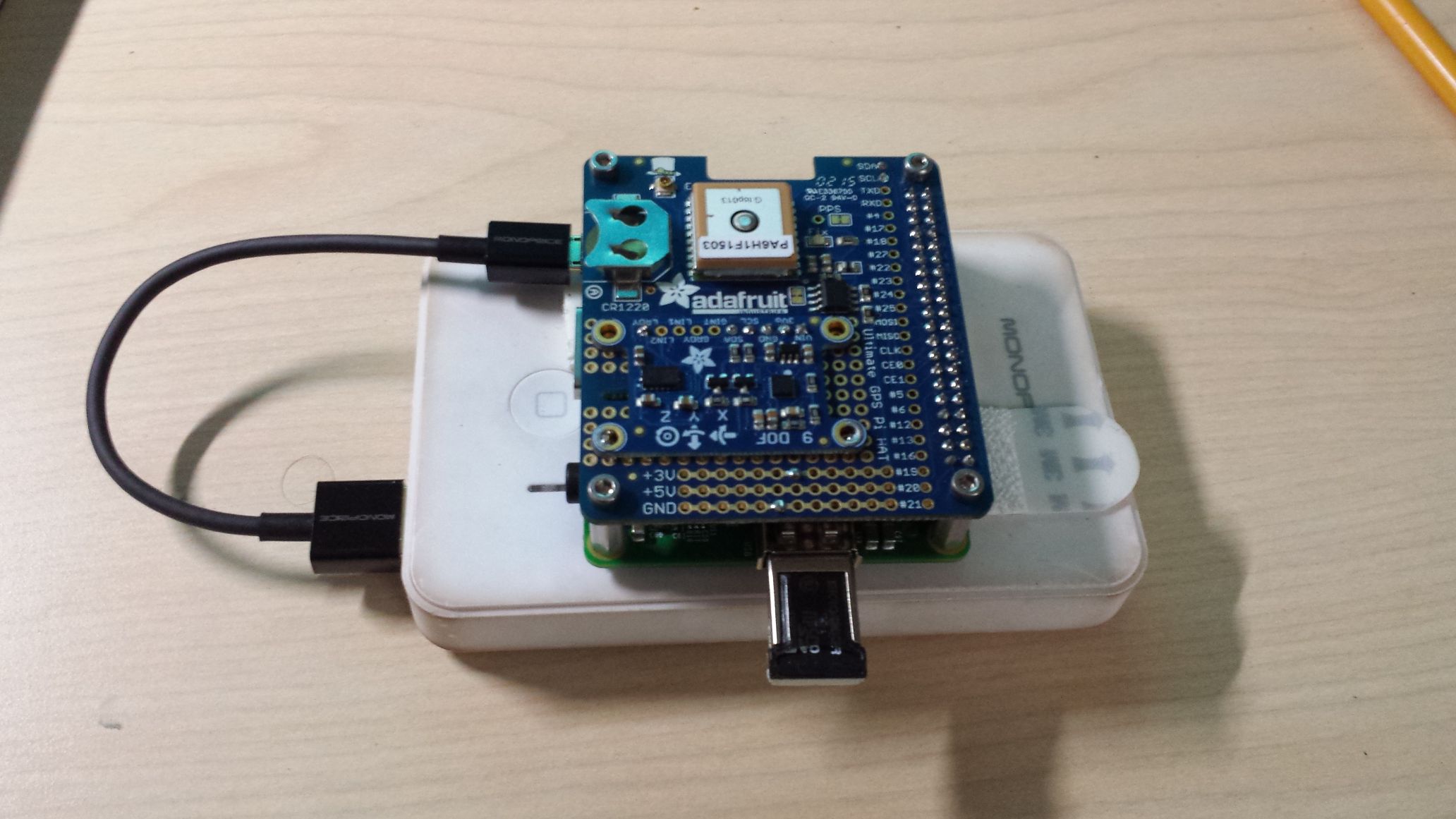
- Generic USB battery pack for portability
- Old flash drive and short USB micro cable
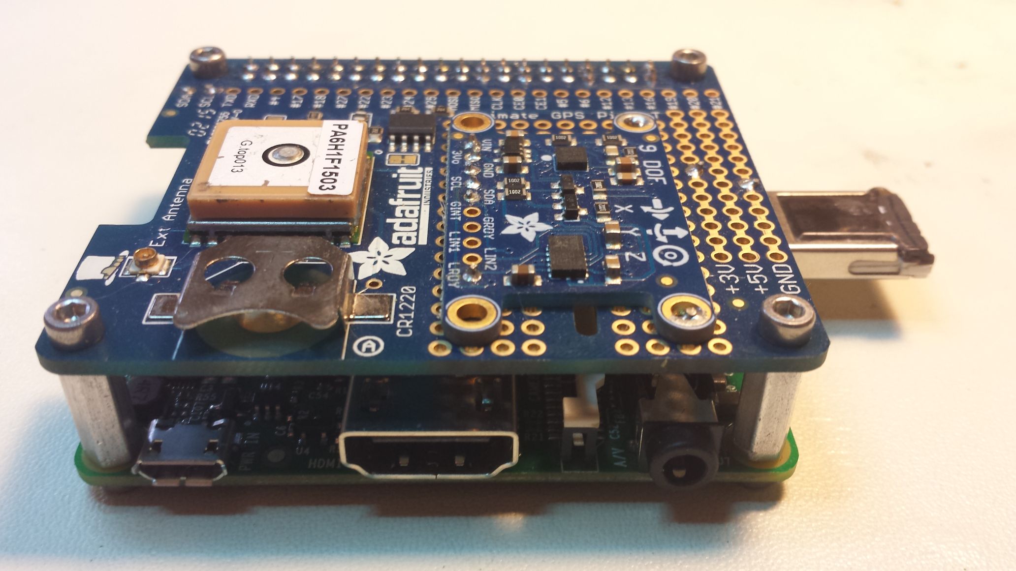
Raspberry Pi Model A+
The Model A+ was the perfect choice for this application, since I already had one, it was a compact form-factor, my application only needed 1 USB port, and the project did not require Ethernet nor a significant amount of CPU power. At this point in time (2015) the Raspberry Pi 2 was available with much more processing power, so this was a good application for which to dedicate this Pi.
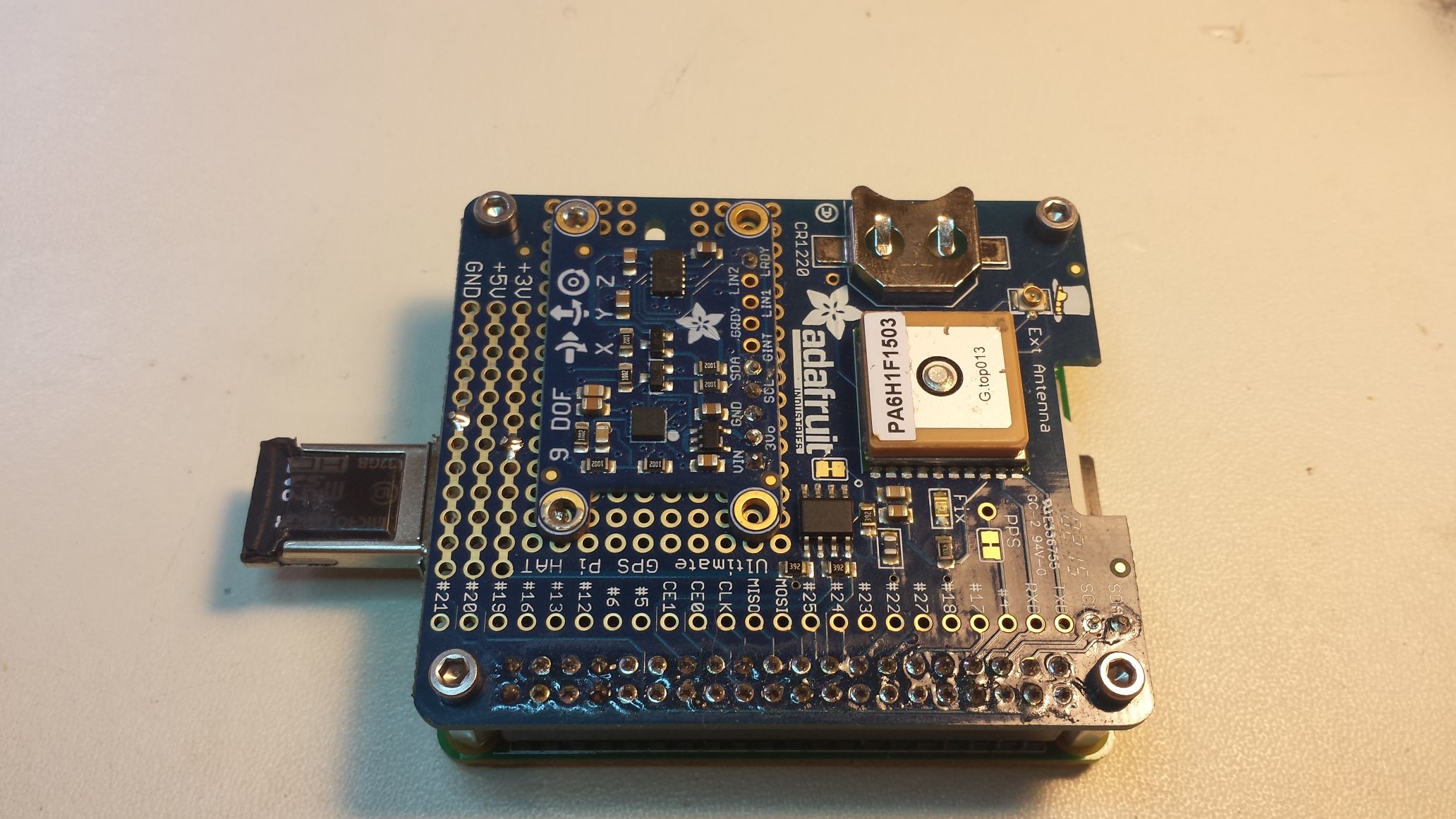
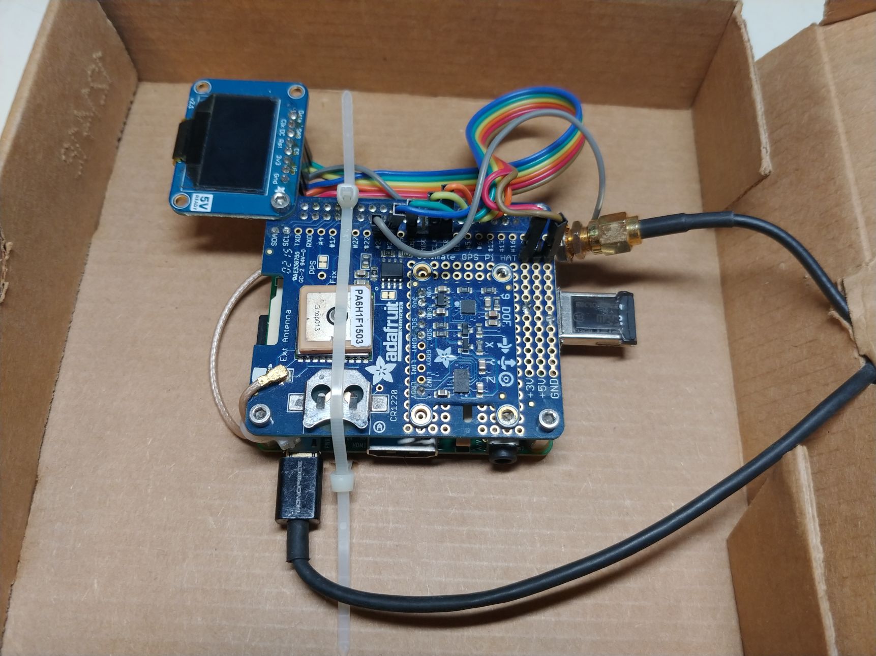
GPS module
The Adafruit Ultimate GPS Hat includes a FGPMMOPA6B GPS module, which uses a MediaTek MT3329 with a ceramic patch antenna on top of the module, as well as support for an external antenna via a u.FL connector. It connects over serial on the Raspberry Pi header (which is generally assigned to /dev/ttyAMA0).
Inertial Measurement Unit (IMU)
I had an Adafruit 9-DOF IMU. This board includes an LSM303 with a 3-axis compass and 3-axis accelerometer, and an L3GD20H 3-axis gyroscope. The GPS hat has some extra proto space, so I soldered some wires from the board to mount it and connect the communication signals. Both of the IMU IC’s used I2C, so I needed 3.3V, GND, SDA, SCL, and also DRDY for the LSM303. The gyroscope wasn’t needed for this application.
Python Software
The software was written in Python 2.7. The python script is executed on system startup using a cron job. The full script is available below. The script starts with connecting to the IMU, since IMU data is available almost immediately over the I2C port. For convenience, I used the Adafruit_LSM303 library, to connect to the IMU and extract the roll, pitch, and heading data from the magnetometer and accelerometer. The gyroscope data was not required.
Next, it connects to the GPS module. It sends several $PMTK NMEA configuration strings to change the baud rate from 9600 to 115200, configure which NMEA navigation strings are sent, and set the device update rate to 10 Hz instead of the default 1 Hz.
$PMTK251,115200*1F 					# change baud rate to 115200 baud
$PMTK314,0,1,0,1,0,0,0,0,0,0,0,0,0,0,0,0,0,0,0*28	# print GPRMC and GGA strings only
$PMTK220,100*2F						# set GPS update rate to 10 Hz
Then it begins parsing all of the NMEA strings as they are received, and waits until a GPS lock is detected. The GPS lock is detected by looking at the recommended minimum specific GPS/ data word $GPRMC, when the 2nd parameter changes from a “V” (invalid data) to an “A” (valid data).
Once a GPS lock is detected, the software creates a file on the mounted USB drive (/mnt/usbdisk/ is assumed to be mounted) using the current date and time that was obtained from GPS. This file naming convention was important. Since the Pi would not have internet connectivity (the A+ doesn’t have wireless or Ethernet), it has no way to maintain the current time between power cycles without a RTC (real time clock) module and backup battery. Although the GPS module did include an RTC and the hat had a CR1220 coin holder, I did not use the RTC capabilities since I didn’t need to start recording data until a GPS lock was acquired anyway. So it made more sense to just wait for GPS lock and always use GPS time for consistency. The bonus benefit was I had time to insert or swap USB devices while the GPS was acquiring a lock.
After the file is created, the software would continuously log GPS and IMU data in CSV format. It wouldn’t stop unless it ran out of storage space or power was removed. This worked perfectly for our flow of test events. We would frequently execute multiple test events over a period of several days, so using a file name based on date/time made it easy to correlate recorded data to specific test events. I could just plug in the device at the beginning of each test, unplug it when complete, and then do it again for the next test event. No need to download the data between test events unless desired.
Testing
My Raspberry Pi GPS tracker worked flawlessly. After a few test flights, I compared the GPS data of my device and our other data recorders using Google Earth, overlaying the tracks. There was almost no discernible difference. When I sent my data to our data scientists for comparison, they found my data to be just as useful. In fact, there were several missions where our normal data recording devices failed, and the data from my tracker was the only available data. It worked great!
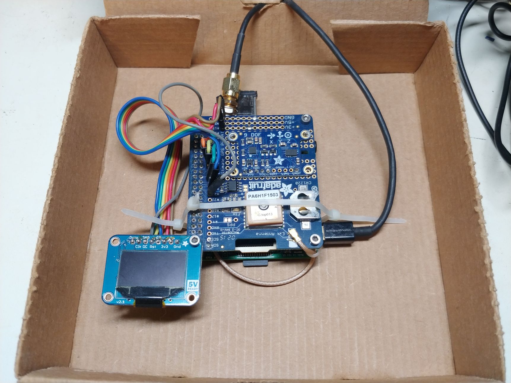
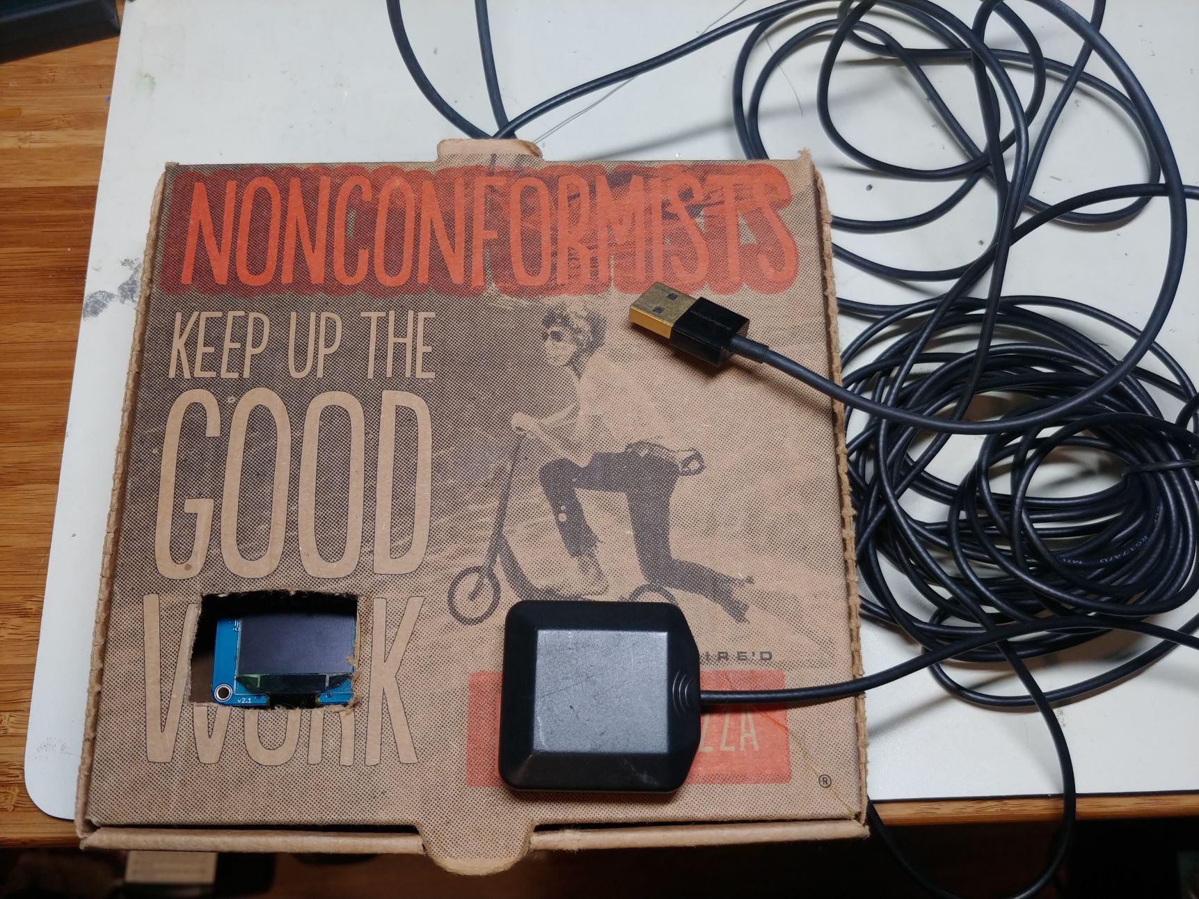
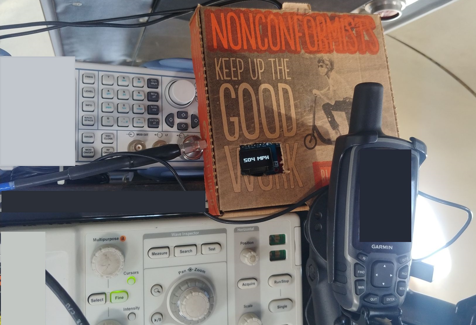
After a few months of testing with the portable version, we had a series of tests on a jet aircraft. I had access to a USB port for power, but I needed to use an external GPS antenna to place it in the window to get a clear view of the sky. I added a simple uFL to SMA adapter with an SMA GPS antenna. I also added an I2C OLED screen (connected to the SPI port on the hat) to display the current GPS speed. And then I shoved everything into a small pizza box, because it was the best enclosure I could find while traveling. This allowed me to fit the long power and GPS antenna cables into the box when transporting the device.
Future
If I were ever going to enhance this project, I would likely use an ESP32 instead of a Raspberry Pi. I would make a custom PCB to include the GPS module, IMU sensors, and a micro SD slot. This approach could make the device consume significantly less power, as the Raspberry Pi is still running a full Linux operating system in addition to the relatively simple Python script. An ESP32 can easily implement this logic and write out data to a microSD card, and the decreased power consumption would mean longer battery life.
Downloads
- Note: Adafruit library dependencies included
- Note: xgf.py - full Python 2.7 script
- Note: xgf-nmea.py - simplified Python 2.7 script that only exports raw NMEA strings
Design Implementation: 2015, 2019
Writeup: Feb 2023
Page Tools
